
Design of a LiDAR
A novel mechanical Lidar design is created, which proposes two axes rotation with only one actuator. This enables the construction of a 3D map using only one motor and one rangefinder, reducing Lidar’s cost.
A combination of gear, worm gear, and planetary gear is used to enable two axes rotation with only one axis torque input.
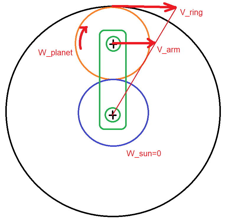
MSC Adams
At first, the proposed gear combination is dynamically simulated in MSC ADAMS, which is a multibody dynamic simulation software. Results verified that the rangefinder (red) moved one degree upwards in each revolution of the motor, which is connected to the arm (yellow). The relative rotation speeds of the ring gear and the worm gear enable this motion of the laser sensor.
Solidworks
The design is finalized in Solidworks by adding all other components like supports, slip ring, and cover, which holds the rangefinder. Static simulation is carried out to confirm the device’s mechanical resistance against static failure.
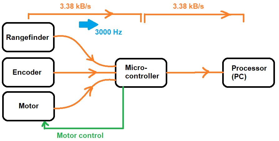
Data Transfer Calculations
The microcontroller is chosen according to the necessary data transfer speed and amount. Data sizes regarding the three defining coordinates are shown below:
- Vertical angle: 7 bit. Vertical field of view is 120° with 1° resolution, 7 bit = $2^7$ = 128
- Horizontal angle: 9 bit. Horizontal field of view is 360° with 1° resolution, 9 bit = $2^9$ = 512
- Distance: 11 bit. Range is 20 m with 1 cm resolution, 0.00 – 20.00, 11 bit = $2^{11}$ = 2048
Optimization of Gear Parameters
Specialties of the number of teeth, diameter, module, and face width of the gears are optimized in Matlab.
The following checks are done in Matlab:
- There must be no interference.
- Contact ratio should be greater than 1.4.
- Pitch line velocity should not be too large in case of high dynamic effects.
Governing equations and constraints:
- $w_{ring} = (w_{ring} - w_{arm}) (360 / N_{gear})$
Gear should rotate one degree in each revolution of the arm.
- $w_{arm} / w_{ring} = N_{ring} / (N_{sun} + N_{ring})$
Pitch line velocity must be the same at the contact point.
- $r_{worm} + r_{gear} = r_{sun} + d_{planet}$
Rangefinder must be vertically aligned with the edge of the planet gear.
Main Components
- Rangefinder:
- Lite v3HP
- Microcontroller:
- Arduino Uno
- Motor-Encoder:
- Pololu brand DC motor with 1030 rpm, 9.7:1 reducer ratio, 48 ppr
- Slip Ring:
- Hollow shaft slip ring
- Gears:
- Module: 4 mm
- Face width: 40 mm
- Pressure angle: 20°